Documents
drawings_information_parr_5410.pdf
equilabo_offer_details.pdf
Technical details
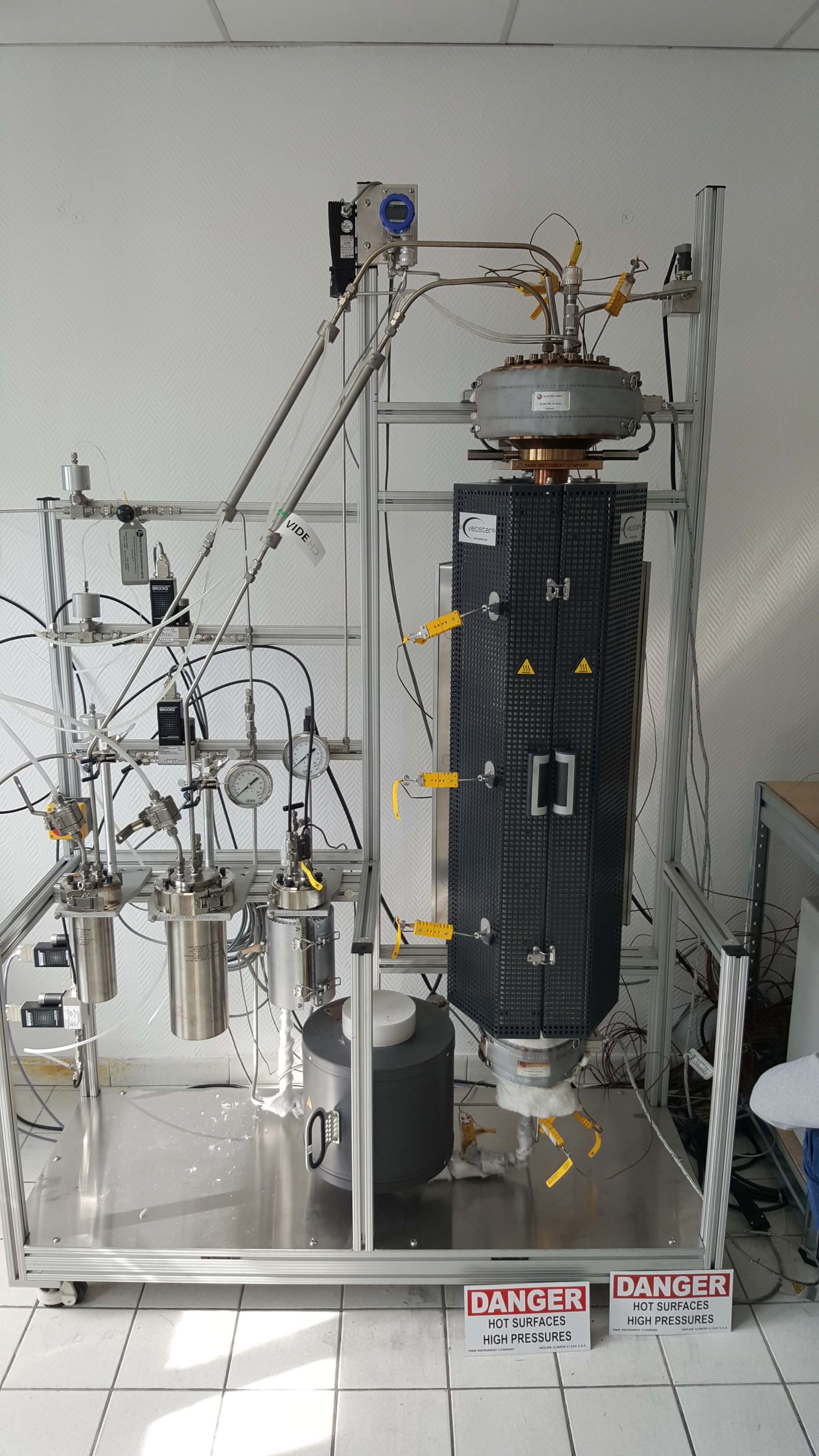
The distinguishing feature of a fluidised bed reactor is that the bed of solid particles or catalyst is supported by a rising gas stream. This reactor allows the catalyst to be easily loaded and removed. This is advantageous when the solids bed has to be removed and replaced frequently. High conversion at high throughput is possible with this style of reactor. These reactors inherently have excellent heat transfer and mixing characteristics.
GAS FEED:
Two reactant gas feed lines, each with normally-closed automated pneumatic shut-off valve, filter, bypass valve, and reverse-flow check valve. One gas feed line has a mass flow controller sized for up to 0.5-25 SLPM of nitrogen with up to 2 bar delivery pressure. The other gas feed line has a mass flow controller rated for up to 50 SLPM of nitrogen flow at up to 2 bar delivery pressure. The maximum inlet pressure for each MFC is 145 psi (10 bar). A purge line is included with automated normally-open pneumatic shutoff valve, filter, metering valve, and reverse-flow check valve. The
automated valve control box requires 105 psig (7.2 barg) dry air or N2 supply for operation. Up to 50 SLPM of nitrogen can be pre-heated to a maximum of 600 °C in a gas preheater upstream of the fluidized bed reactor inlet. This preheater can also vaporize up to 10 mL/min of liquid feed while feeding up to 25 SLPM of nitrogen or other gas.
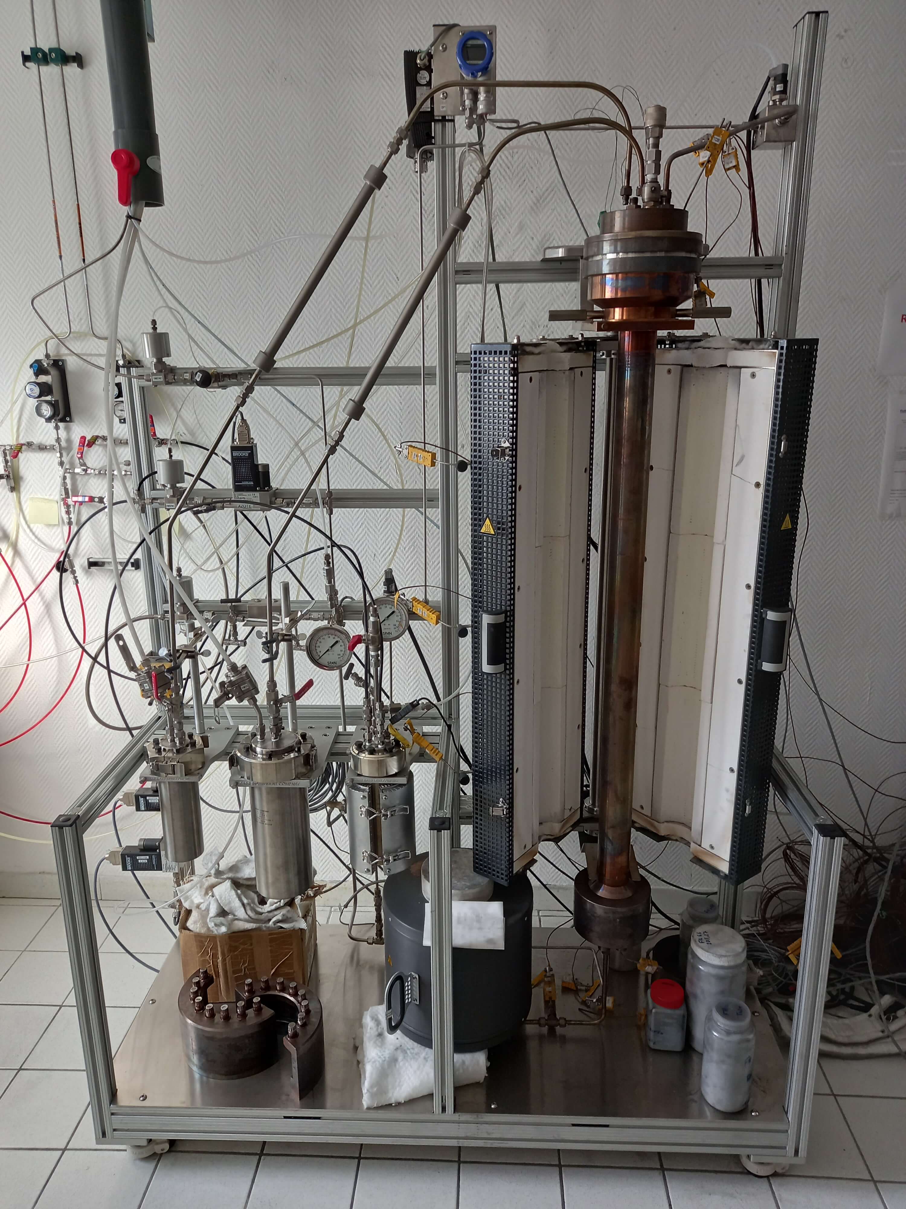
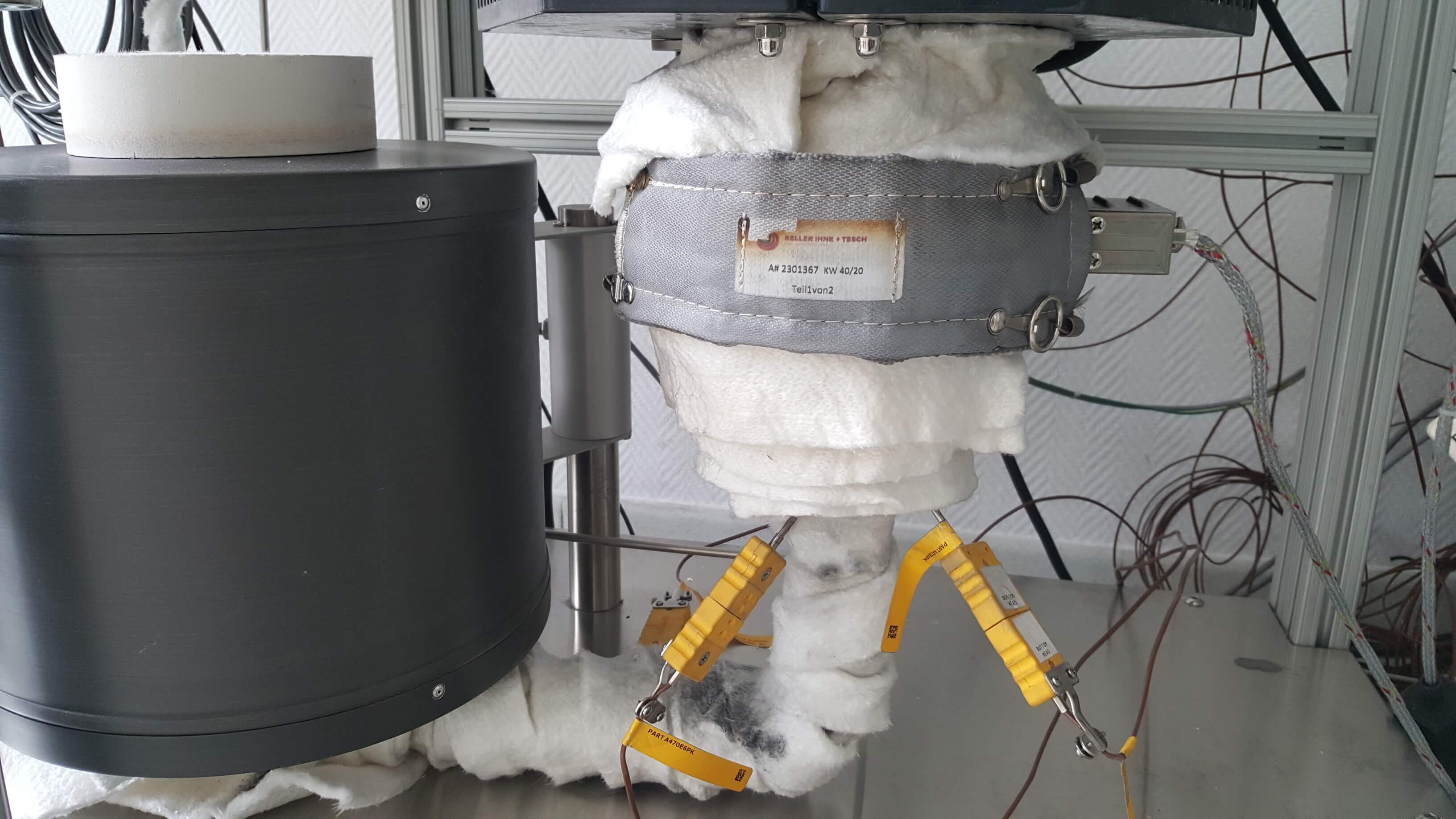
REACTOR MODULE:
One 5410 T316SS Fluidized Bed Reactor Assembly, rated for use up to 36 psi (2.5 bar) at 750 °C with removable internal 0.25-inch (6 mm) OD T316SS thermowell and 0.090 (2 mm) OD moveable 3-point Type K thermocouple. The reactor assembly includes a 45-inch (114 cm) long reactor tube with a three 12-inch heated zones for total of 36- inch (91 cm) heated length and 2-inch (50 mm) internal diameter with 5.5-inch (14 cm) ID particle disengagement zone at the top and and split ring head closures with metal gaskets at each end. Module also includes a 600 psi (41 bar) Alloy 600 safety rupture disc, a 30 psig (2 bar) pressure relief valve, a 30 psi (2 bar) 316 SS pressure gage, and a 30 psi (2 bar) pressure transducer at the inlet and outlet. A 1 psi (70 mbar +/- 0.4 mbar) differential pressure transducer is also included. Reactor is heated in a three 12-inch- zones of 36 inches (as well as heaters on inlet and outlet heads rated to 600 °C) (1850 cm3 total heated internal volume in annulus around thermowell) by a Fluid Bed Split Tube + End Heaters furnace (230 VAC) with control thermocouples on the outer reactor wall at the center of the length of each heated zone. Solids addition port with water cooled sleeve is included for addition of solids to the hot reactor in the absence of internal pressure or flow.
PRODUCT RECOVERY AND SAMPLING:
Gases exiting the reactor pass through a T316SS cooling condenser. A parallel path particulate recovery line bypasses the particle disengagement zone via dip tube to allow evacuation of the particle bed from the hot reactor when desired. The gas exit line and the particle recovery line each have a dedicated T316SS cooling condenser, a high temperature ball valve rated to 450 C, and are connected to the 2000 mL T316SS solids recovery vessel with 0.5 micron filter and high temperature needle valve on the gas outlet.
CONTROL and DATA ACQUISITION SYSTEM:
Model 4871B process controller, two 4876A heater controllers, and a 4877 valve control box are included, requiring 230 VAC. The 4871B controller is equipped with two 8-channel analog input modules to monitor gas flow rate, reactor temperatures and system pressures; two 16-channel digital output modules to control reactor heating, automated valves, and pump on/off; one 16-channel digital input card for remote emergency stop button; and one 4-channel analog output module for gas flow rate set points. Software for system operation is supplied on a USB drive, including control, monitoring, and data logging software for use with a user-supplied PC. Cables from the controllers to the system are 30-ft (9.1 m) in length. This system is offered as a fully assembled and tested unit, mounted on a floor stand having a typical maximum assembled height x depth x width of 84-inches (213 cm) x 22-inches (56 cm) x 48-inches (122 cm). The system is warranted for a period of 12 months.